Back to the Future Digital Speedometer: Making a Replica
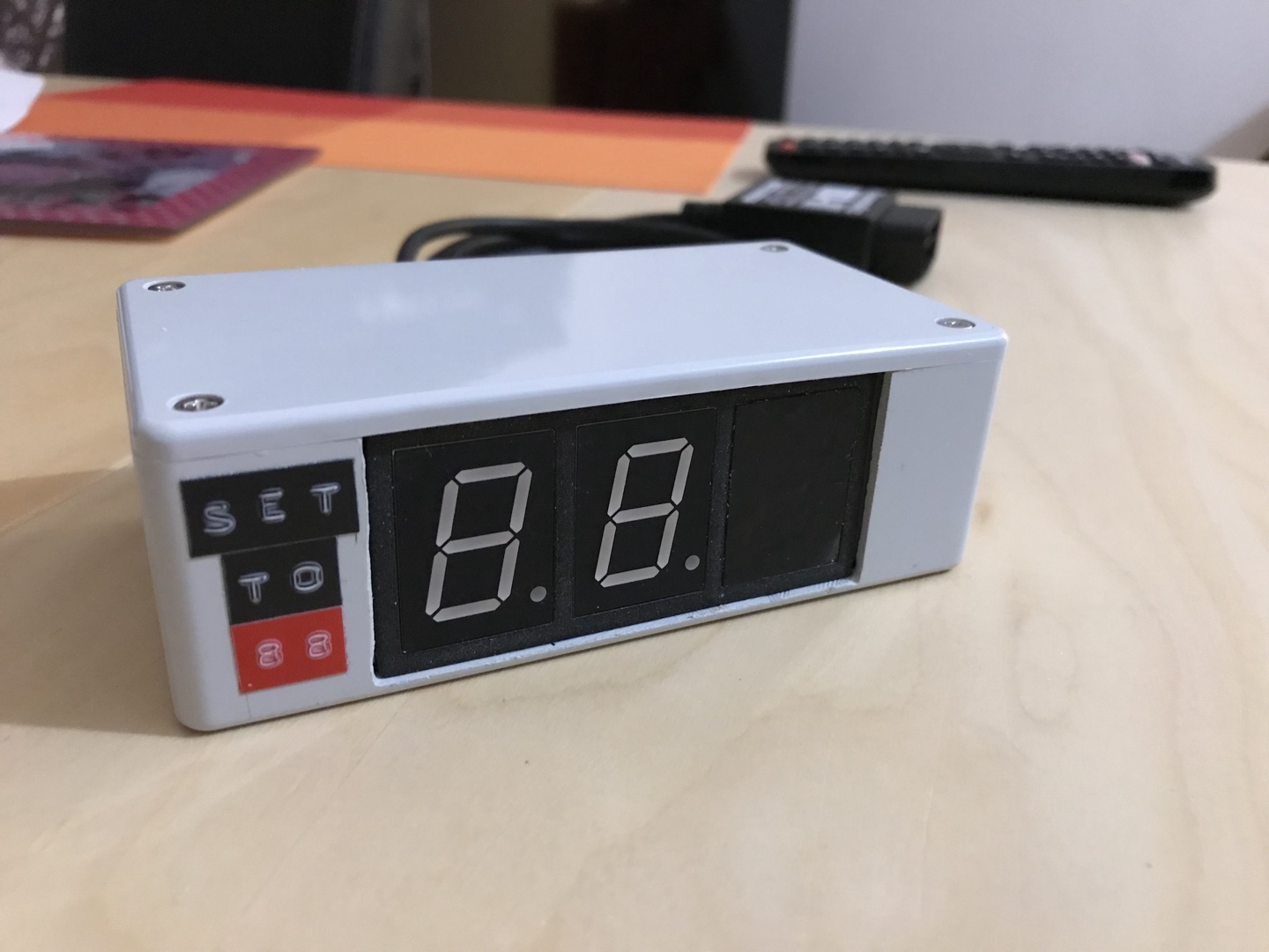
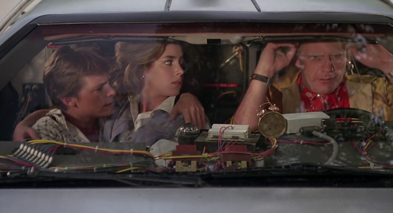
For a long time now, I’ve been wanting to create a replica of Back to the Future’s digital speedometer. It’s a prop used in the movie that’s placed on the DeLorean’s dashboard, and can be seen multiple times throughout the trilogy. Of course, it’s mostly used as a visual element to mark when the DeLorean reaches 88 miles per hour and begins its time travel!
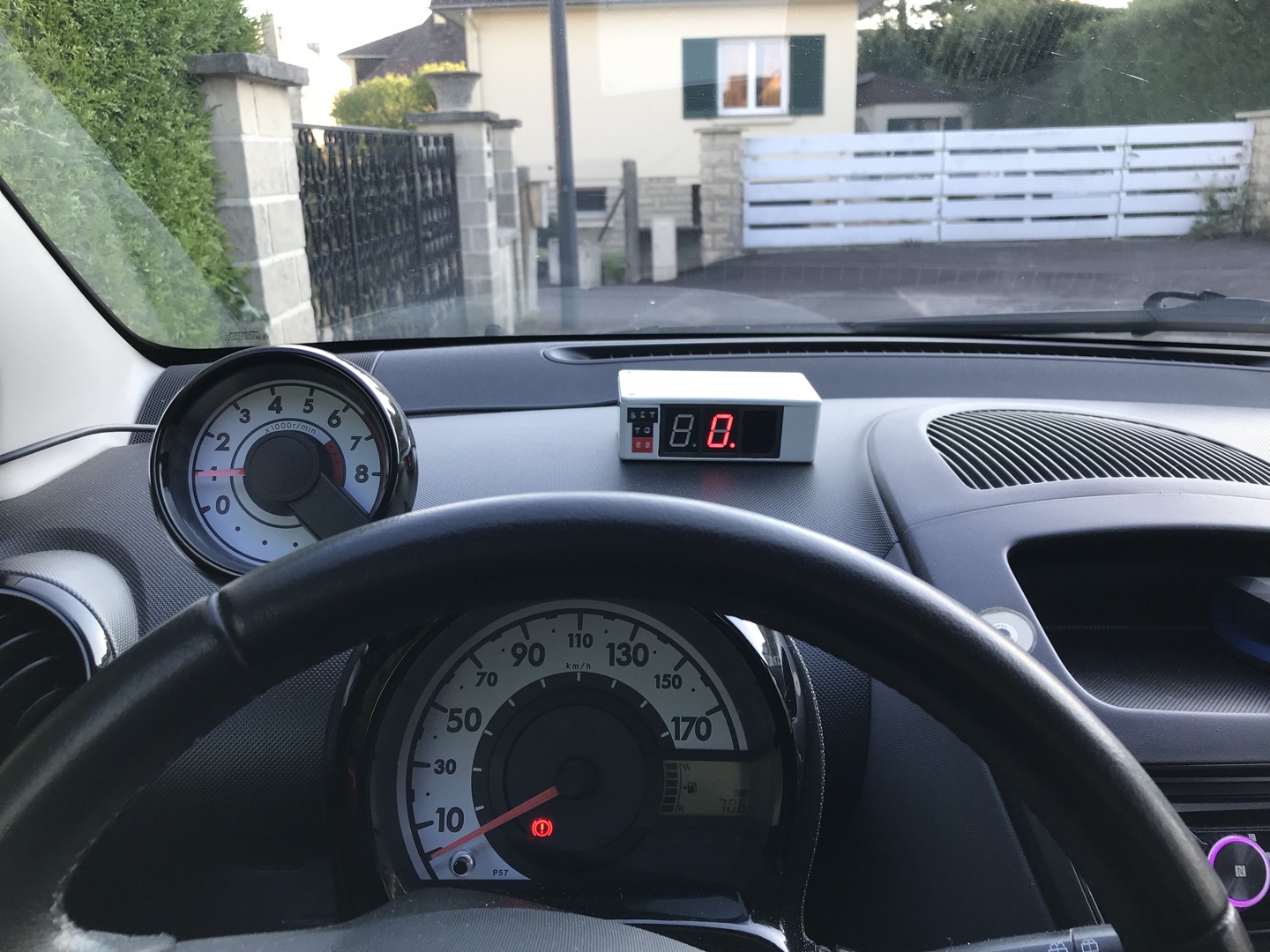
I thought it would be cool to recreate it, and make it compatible with modern cars. I’ve seen very good-looking GPS models on the market, but I wanted to make something more genuine. GPS feels like cheating! There’s also a really awesome replica made by Damien De Meulemester that only uses components available in 1985, and works on a real DeLorean by adding a sensor to the speedometer. This is way out of my league, and obviously out of the question for modern cars with electronic speedometers, but it was a great inspiration to get started on this project.

I settled on making my replica connect via a wire to the car’s OBD-II port, which is present on the vast majority of today’s cars.
Resources
You can find the firmware’s source code, reference material, CAD files, and more on Github.
Preparing the build: research!
We have to figure out the dimensions of the prop, the materials and components used, etc. Thankfully, the Internet is a great resource, and people have already done most of that for us.
The enclosure used in the movie is apparently a Hammond 1591CGY ABS box. It’s 120 x 65 mm, so it’s not too big for a dashboard, and has a pretty good size for fitting some electronics in it.
The displays used in the movie are three Stanley readout displays, which, unfortunately, don’t exist anymore. This technology has largely been replaced by seven-segment LED displays, and since they’re so similar, we’ll use these. The dimensions are tricky; it’s difficult to find the exact right size, but displays with a digit height of 20.3 mm seem to do the trick nicely. I’ll be using three Multicomp LS0803SRWK for this project.
Note that the third digit is hidden by a piece of tape; to keep things simple but accurate and more power-efficient, we’ll use a third display, but without wiring it.
The Stanley readout displays used to come with a black frame around them, which we can see in the movie. We’ll have to do without this. There are multiple solutions, including cutting a polystyrene frame, or using a sheet of black plastic, but the most elegant solution in 2017 to my eyes is 3D-printing a nice, sturdy plastic frame. If you’re using displays similar to mine in dimensions, you can use this model I made.
At the end of the first movie, we can see the back of the speedometer a little bit better.

As you can see, it’s using some kind of DB25 sub-D plug, which is usually found on old computers as a parallel port (used for printers and such). Not terribly convenient, but not too hard to find!
The Dymo labels found on the front of the box—famously reading SET TO 88—might be one of the trickiest to reproduce today, if you don’t have the right hardware. Modern Dymo machines usually print in 2D using a different font, but the labels we need are 3D (embossed) and 12 mm high. 9 mm embossed labels can be found, but 12 mm ones are rarer.
We’re now mostly good on our “exterior” stuff; our speedometer should be pretty good-looking if we can get all of these parts.
Build process
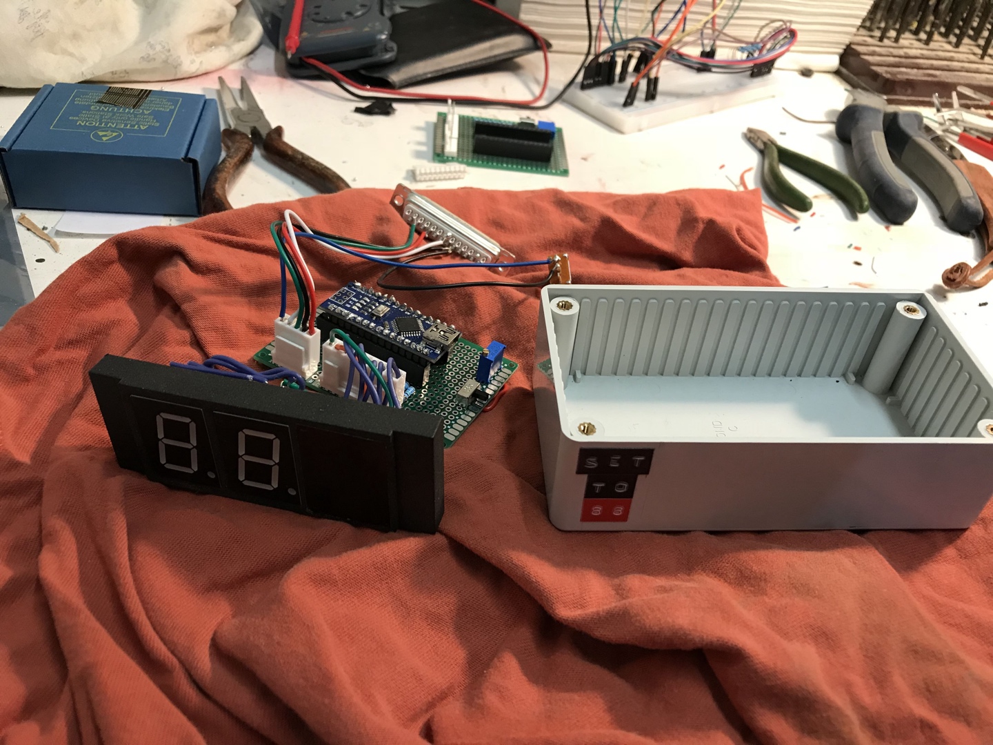
I’m using an Arduino Nano (compatible) board for this project. It’s got a UART interface, enough I/O ports, and runs at 5V. It’s also super tiny and will fit nicely in the enclosure.
We’ll need to get our Arduino to communicate with the car’s CAN bus to get the vehicle speed. Fortunately, this is all pretty easy, using the Freematics UART OBD-II adapter; it’s made for Arduino and provides a simple ELM327 interface that’s compatible with most CAN standards. It can even provide power to the board and has simple-to-use libraries, so it’s perfect for our needs.
I had some creative choices to make when it comes to the build. I chose to include an ON/OFF slider on the back, next to the plug, to make sure the speedometer doesn’t drain the battery when the engine is off. It’s not a hard switch: it signals the Arduino to put itself and the Freematics adapter into sleep mode. I also included a speed adjustment potentiometer which you can use to calibrate the display with your actual speed.

The Arduino’s firmware development was a tough task, as I had to learn a lot about interrupts, serial communication and display driving in the process. In the end, it’s designed as a state machine with three states (sleep, connecting, connected).
The 7-segment displays are driven using a fork of the SevSeg library that tweaks the segments to reflect the ones used on screen (no top/bottom bar on 6 and 9, respectively) and always displaying the decimal point.
The OBD data is polled often, and when we get the current vehicle speed, we display it by going through all the numbers in between (with a linear interpolation). That was a very important point for me, because that’s how it is on screen, and no replica seemed to do this except for De Meulemester’s.
I started by making a basic prototype of the logic board on a breadboard and trying to make it work as well as possible with my car. I got into trouble when it came to interrupts and took a while to finish that whole system; I worked on the hardware parts in the mean time.
Once I had a working prototype, I finally could solder the whole thing (which also took some effort) and put it into its box!
Retrospective
This was a great project to both attempt to build hardware and play with Arduino. The electronics involved are pretty simple but still made me ask some interesting questions that are definitely useful in any project: What’s a pull-up resistor and why is it needed? How do you wire multiple 7-segment displays, and what is multiplexing? How do you handle interrupts and switch between different tasks at the same time (boy was that a tricky one).
I’ve made a few mistakes, of course, and there is certainly a lot to be improved by more skilled DIY-and-BTTF-enthusiasts (if you’re one of them and decide to follow my steps, please send me a tweet 👌).
Using Molex connectors was, in retrospect, not such a good idea. I thought it would improve modularity; but whereas in computer science that doesn’t mean many drawbacks, in electronics it means wasted space. The enclosure isn’t that small, but the connectors are pretty big and I certainly could have done without them and the long-ass cables I used for them.

I could probably also improve the constant polling of the serial line, linear speed interpolation (using the accelerometer data that comes with the adapter?), and display multiplexing.
Overall, this was a lot of fun. I hope you liked it too! 😎